Tuesday, November 13, 2007

Funny Message For A Baby Shower

logic AND function.

now seeks to "complicate" a little bit on our circuit. The last time we saw how you can operate a gate either from multiple locations in the circuit by entering simple pneumatic components that act as logical operators OR. In this post we will know a operarore other logical AND operator. We will see that it is possible, by connecting more valves, re-create an AND operator without using additional components and therefore complicate the circuit.

We refer to this more at the gate of Figure 9.

We wonder what we foresee in the circuit of an automatic gate opener if we are to meet the following assumptions:
  • the opening command should only intervene if the gate is closed;
  • closing command should intervene only if the gate is open.
To fulfill these requirements we need signs to indicate that the gate is open or closed. Prepare the button that is activated when the gate is open and one when it is closed. The buttons that perform this task are those that are generally switch valves 3 / 2 NC controlled mechanically, in our case from the gate that ends its rotation (Fig. 9).
Because the gate can be opened by activating V2 or V2 'must be on the limit FC2. Conversely, because the gate will close by activating V1 and V1 'must be on the limit FC1. To achieve these conditions the limit switches and valves must be connected to AND together as shown in Figure 10 in the case of V2 and FC2.


fig. 10 - Circuit diagram of the logic AND function.


Table 3 summarizes all the possible combinations between V2 and FC2 connected to AND.

Table 3 - Summary of possible combinations of FC2 and V2 connected to AND.
If we use the digits "0" and "1" as was done for the logic OR function yields the following truth table.

Table 4 - Table of V2 and FC2 connected to AND.


In summary we can say that only if V2 and FC2 are simultaneously active generating the output signal from the valve and then the AND gate opens.


OBSERVATION
To get a link, simply AND of two valves connected in series. In this way, in fact, the signal can pass only if both valves are active (Fig. 11).

fig. 11 - AND being made in connection with standard valves.

<-- Previous Post Next Post ->

Sunday, November 4, 2007

Dark Brown Hair Pale Skin

logic OR function.

Today I would like to highlight some solutions that can be taken when handling must be controlled from multiple locations. We introduce in particular the use of pneumatic circuit elements that allow to create some logical operators . Maybe some of you have heard of Boolean algebra . Anyway I will try to introduce only the concepts that may be useful for the realization of plans for moving the gate Figure 3.


Suppose then that it is the gate of a villa and as such should be able to be operated both from the ground floor from the upper deck. There will be two pairs of buttons V1, V2 and V1 ', V2', one for each floor, which create the same signals for opening or closing the gate. In other words, pressing V1 or V1 '(or both together) you must generate the signal "close". The same applies to V2 and V2 'and the sign "OPEN". The conditions described above are defined OR and can be summarized as in Table 1 if, for example, the gate is initially closed.


Table 1 - Combima of V2 and V2 'connected in OR.

If we now associate with the digit "0" button is not pressed to the states and absence of the output signal from the valve ring and the number "1" states of the button pressed and the presence of the output signal is obtained from the OR table 2 that Table of .


tab. 2 - Table of the OR function.


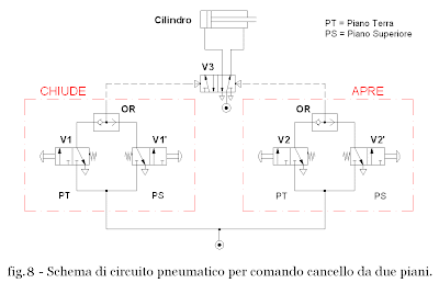
Figure 7 shows the schematic for the realization of a logic OR function. In the light of it we can make the following considerations:

  1. If no buttons are pressed does not generate any signal;
  2. Pressing the button only V2 generates the signal that arrives at the valve ring which makes no reference to generating the signal "OPEN" in output;
  3. press button only to V2 'signal is generated that goes to the valve ring which is passed by creating the sign "OPEN" outgoing
  4. Pressing both buttons generated the two signals arrive at the valve ring that makes them move at the same time generating the signal "OPEN" in output.

Only in the first case the gate is stationary. In all other cases the output signal from the valve is opened when the OR gate. The same is true for the valves V1 and V1 'and the signal "close".

diagram of the pneumatic circuit to handle gate controlled by the two plans is shown in Figure 8.


<-- Previous Post Next Post ->

Florida Where To Buy Morton Tender Quick Salt

Bibliography.


[1] Caligaris, L., Fava, S., Tomasello, C., TeknoMech. Mechanical technology and Laboratory, Hoepli, Milan, 2003.

[2] Giaquinto, D., Rubin, S., Automation, Editrice San Marco, Bergamo, 2006.

Saturday, November 3, 2007

Cazal 856 Vintage Replica

handling of a gate - solution 2. First

We can "improve" the circuit seen in the previous post in the scheme by introducing a command for opening and closing a "memory". If the signals generated by valves V 1 and V 2 are used as control signals for switching a valve V 3 5 / 2 bistable linked to the two cylinder chambers, you get the diagram in figure 5.
Pressing V 2 its signal will toggle the V 3 which connects to drain the left chamber of the cylinder and directs the flow of compressed air to the room right of the stem and resulting in a return gate opening. Even if you release the button, the valve V 3 stays in place keeping the pressure in the cylinder chamber thereby blocking the stem. Instead by pressing the V1 to V3 its signal does switch back room that connects the right to discharge and direct the flow in the left chamber of the cylinder resulting in leakage of the rod and closing the gate.
Wanting now complete the pattern we must remember that the c ircu control (dotted line) must be supplied at low pressure while the power (solid line) at high pressure. To satisfy this condition we have to install a pressure reducer upstream of the valves 3 / 2 in order to bring pressure to values \u200b\u200bcompatible with the control circuit (c p = 2 bar ). By introducing this new component of the circuit diagram is shown in Figure 6.


summarize the FRL group feeding pressure p p = 6 bar the main line that branches from one party to the V3 valve that alternately feeds the two chambers of the cylinder, the other to a pressure that feeds the V1 and V2 with a pressure c p = 2 bar .

<-- Previous Post Next Post ->

Thursday, November 1, 2007

Kates Playgorund Unscensor

simple pneumatic diagrams.

A pattern tire is a graphical representation of the set of pneumatic components, properly linked together, for the operation of a system handling. We will study the forms of tires trying to find solutions to real problems.

F4.2.1 handling of a gate - Solution 1.
Suppose we want to make a pneumatic system that allows you to open and close a gate by pressing two buttons (Fig. 3).
This problem can be solved in different ways and each solution requires the study to be analyzed before the elements necessary to achieve the required functions. For the movement of the gate is necessary that:
  • you use an actuator, in this case a cylinder, able to open and close;
  • that the cylinder can work in both directions.

The above conditions can be met by a double acting cylinder is positioned as shown in Figure 3.
The gate opens when the cylinder rod falls and closes when the cylinder rod is forced to leave. In other words, it is necessary that the flow of air under pressure alternately put the two chambers of the cylinder, also when a cylinder chamber is pressurized and the other must be discharging and vice versa. To reverse the flow using two selector valves that will be chosen to satisfy the above conditions.

In the first instance we can use two valves 3 / 2 NC monostable connected to the two cylinder chambers. Is obtained in this way the circuit diagram shown in Figure 4.

The V2 valve manually operated push button directs the flow of compressed air in the room right of the cylinder with consequent return of the stem moves the gate opening. On the contrary, the valve V1, which is also controlled manually, directs the flow of compressed air in the left chamber of the cylinder resulting in leakage of the rod that pushes the gate closes.
is easy to see that in both cases, when you release the button the cylinder chamber is not pressurized and the piston is not locked, that is pushing it moves. This is due to the fact that in the rest, the two valves connecting the chambers of the cylinder to exhaust. This situation makes us understand that we have found a solution to the problem proposed but we have not found the best solution.

<-- Previous Post Next Post ->