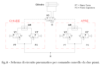
Today I would like to highlight some solutions that can be taken when handling must be controlled from multiple locations. We introduce in particular the use of pneumatic circuit elements that allow to create some logical operators . Maybe some of you have heard of Boolean algebra . Anyway I will try to introduce only the concepts that may be useful for the realization of plans for moving the gate Figure 3.
Suppose then that it is the gate of a villa and as such should be able to be operated both from the ground floor from the upper deck. There will be two pairs of buttons V1, V2 and V1 ', V2', one for each floor, which create the same signals for opening or closing the gate. In other words, pressing V1 or V1 '(or both together) you must generate the signal "close". The same applies to V2 and V2 'and the sign "OPEN". The conditions described above are defined OR and can be summarized as in Table 1 if, for example, the gate is initially closed.
Table 1 - Combima of V2 and V2 'connected in OR. 

If we now associate with the digit "0" button is not pressed to the states and absence of the output signal from the valve ring and the number "1" states of the button pressed and the presence of the output signal is obtained from the OR table 2 that Table of .
tab. 2 - Table of the OR function. 
Figure 7 shows the schematic for the realization of a logic OR function. In the light of it we can make the following considerations:
- If no buttons are pressed does not generate any signal;
- Pressing the button only V2 generates the signal that arrives at the valve ring which makes no reference to generating the signal "OPEN" in output;
- press button only to V2 'signal is generated that goes to the valve ring which is passed by creating the sign "OPEN" outgoing
- Pressing both buttons generated the two signals arrive at the valve ring that makes them move at the same time generating the signal "OPEN" in output.

Only in the first case the gate is stationary. In all other cases the output signal from the valve is opened when the OR gate. The same is true for the valves V1 and V1 'and the signal "close".
diagram of the pneumatic circuit to handle gate controlled by the two plans is shown in Figure 8.

<-- Previous Post Next Post ->
0 comments:
Post a Comment