Sunday, December 9, 2007

Pleaus Can I Have The Ranebow Puffle

Final Note.

This blog is designed for students of second IPIA to address mechanical and hope that it will be useful to them.

The intent of the blog is to communicate some simple techniques that can be used for the construction of small pneumatic circuits. The treatment is for this reason set in order not to be heavy and has lots of pictures and animations.

The lessons follow a timeline demoted from newest to oldest. Council then from the first lesson and to navigate within the blog using the hyperlinks here and there or take links the archive of the blog.

I teach in a vocational school and my students are very passionate about this subject. I hope this blog can do excite other students.

the next.
Gianluca Ferraro

Sharpest Chefs Knives

Example of automatic industrial.

Suppose we want to build a circuit that solves the problem of handling materials depicted in Figure 17. A box must pass by a conveyor belt to another. Identifies the following phases:
  • 1. The tape T1 port box in position 1 and stop;
  • 2. The stem of the cylinder A, activated by a start button, lifting the box out to position 2;
  • 3. The stem of the cylinder B by pushing out the box on the tape T2
  • 4. When the box is on T2 within the stem of A;
  • 5. When he returned to T1 wakes up and is part B.

fig. 17 - System of a materials handling equipment.

Each cylinder must be equipped with two switches: A0 and A1 for the cylinder A, B0 and B1 for the cylinder B. The sequence to be generated is A +, B +, A-, B-and because, at rest, the stems are returned to their limits both A0 and B0 are active. Here are the phases of motion of the circuit:

  • You press S connected AND with B0 à It generates the signal A +;
  • The stem of the cylinder A, ended its run out, turn on the switch A1 generating the signal B +;
  • The rod B, which ended its run, activates the limit switch B1 signal generating A-;
  • The stem of A falls and activates the limit A0 signal generating B-;
  • Finally the stem of the switch activates B B0;
  • S Pressing the cycle starts again.

phases of motion can be represented graphically what is called phase diagram or Ciclogramma (Fig. 18). The x-axis shows the time and the ordinates Stroke.


fig. 18 - Diagram of the stages of the sequence A +, B +, A-, B-.


tab. 8 - Overview of the automatic cycle A +, B +, A-, B-.

lists the components required for the realization of the circuit:

  • No 2-cylinder de;
  • No 2 selector valves 5 / 2 bistable (one for each cylinder);
  • No 4 limit switches (two for each cylinder);
  • n.1 valves 3 / 2-button (Start button).

For the realization of the key components are placed from top to bottom, connecting the cylinders to the distributors on the latter indicating the control signals from switches, you mark the positions of switches and eventually complement other connections. The circuit diagram is shown in Figure 19.

fig. 19 - Schematic of the pneumatic circuit Materials handling.

As we saw last time, making the continuous loop of the circuit of Figure 19 by replacing the Start button, a mechanical memory circuit. The complete diagram obtained is shown in Figure 20.

fig. 20 - Schematic of the pneumatic circuit that performs the loop A +, B +, A-, B-. In line with current Joint control circuit Start / Stop.

Watch the video of the lesson.

If you are interested in lessons on the circuit simulation and realization to tire let stand a post and your e-mail.

<-- Previous Post Next Post ->

Thursday, December 6, 2007

Water Pump / How To Unthaw

cycles.

The diagrams tires so far seen the signs that have generated the movement of mechanical parts were produced by manual controls outside the process of opening and closing the gate.

DEFINITION
A process is called automatically when the signals are generated that implement the same process.

From the above definition we can deduce that the systems examined above are not automatic.

single automatic cycle
Suppose we want to build a circuit where the touch of a button, leave the stem of a cylinder, which completes its run, and then come back. In this case the return signal is generated from the stem of the stem itself. This process is called single-cycle . It is useful for the preparation of the scheme, dividing the cycle into phases and determine the signals that activate the drafting of the prospectus cons (Table 7).

Table 7 - Overview of the automatic cycle A +, A-.


Con A + indicates the output phase of the stalk with the A-phase Return of the stem and A +, A-indicates the complete cycle. S is the signal coming from the start button, the A0 signal switch input of the stem and the A1 signal switch out the stem. The above statement should be interpreted as follows:
  • signal S generated by the Start set to switch to the distributor generating A0 + A;
  • The switch A1 it transfers the distributor that generates A-.


To realize the circuit so we need:

  • No 1-cylinder de;
  • No A selector valves 5 / 2 bistable pneumatically driven,
  • No 2 limit;
  • No Valves 1 3 / 2 NC-button.
For the construction of the scheme must first place components from top to bottom and then trace the connections:

1. You draw the actuators;
2. It indicates the position of switches with dashes in the vicinity of the stem;
3. We draw all distributors are signals that switch them;
4. We draw the limit;
5. You draw the buttons;
6. We trace the links.

switches are always drawn in the position to take when the system is at rest. The scheme of the circuit under test is shown in Figure 15.

Figure 15 - Schematic of pneumatic system for automatic cycle single A +, A-.


continuous automatic cycle

The schedule just got to have carried out a single cycle circuit A +, A-and then stop until it is done again on the Start button.

DEFINITION

A cycle is defined as automatic continuous press a start button when it is repeated continuously until it is stopped with an external signal.

order for the cycle becomes continuous is therefore necessary that:

  • the stem after it is returned, automatically succeeds;
  • hold the start signal (S) the cycle continues until a signal arrives Stop.

The above conditions are met by replacing the Start button with a memory circuit composed of two mechanical valves 3 / 2 monostable button controlling a valve 3 / 2 bistable M with its own power (Fig. 16).

fig. 16 - Circuit diagram for continuous automatic cycle A +, A-.

At rest, the limit A0 M is active and the valve closed. Pressing the Start (S) you switch the valve M in AND with A0, A + which generates the switching valve 5 / 2 that exits the cylinder rod A. When the stem is released the switch is activated A1 generating the signal that it transfers the A-5 / 2 valve and the stem part. When the stem is returned limit switch is activated AND A0 which is connected with the valve in M \u200b\u200bwhich has remained open: the cycle can start again. To shut down, press the Finish button (F), it transfers the valve M in the "CLOSED". When the cycle is completed in place, and activates the limit A0 valve M is closed and the system stops.

<-- Previous Post Next Post ->

Sunday, December 2, 2007

The Women Online Lektor Pl

logic functions NOT and YES.

Now suppose that the circuit should have a security system that will stop the gate during the race encounters an obstacle. This condition can be satisfied predisponedo a sensor on the gate that blocks the flow of air that feeds the circuit when it is operated. This sensor can be a button valve 3 / 2 NA (N Button Figure 9) that lets air in normal conditions and when pressed it locks the transition (Fig. 12). The signal of the button N denies the passage of air for which this type of valve is defined as NOT.

fig. 12 - logical NOT function .
assigning "0 / 1" conditions "absent / present 'signal N input and output signal of the valve will NOT get the truth table on the logical NOT function below.
tab. 5 - Table of truth on the logic function NOT.

Similarly, the logic function allows YES the passage of a signal only in his presence. This function can be realized with a valve 3 / 2 NC, and is usually used for the regeneration of the signals, because all they need is a low-pressure (Y in Fig. 13) to obtain a higher pressure ("Signal" in Fig . 13).

fig. 13 - YES logic function.


tab. 6 - Table of YES on the logic function.


Ultimately we can build the complete diagram of the automated gate controlled by two different planes and with proximity sensor to stop N security (Fig. 14).

fig. 14 - complete pneumatic circuit diagram for the movement of a gate.

<-- Previous Post Next Post ->

Tuesday, November 13, 2007

Funny Message For A Baby Shower

logic AND function.

now seeks to "complicate" a little bit on our circuit. The last time we saw how you can operate a gate either from multiple locations in the circuit by entering simple pneumatic components that act as logical operators OR. In this post we will know a operarore other logical AND operator. We will see that it is possible, by connecting more valves, re-create an AND operator without using additional components and therefore complicate the circuit.

We refer to this more at the gate of Figure 9.

We wonder what we foresee in the circuit of an automatic gate opener if we are to meet the following assumptions:
  • the opening command should only intervene if the gate is closed;
  • closing command should intervene only if the gate is open.
To fulfill these requirements we need signs to indicate that the gate is open or closed. Prepare the button that is activated when the gate is open and one when it is closed. The buttons that perform this task are those that are generally switch valves 3 / 2 NC controlled mechanically, in our case from the gate that ends its rotation (Fig. 9).
Because the gate can be opened by activating V2 or V2 'must be on the limit FC2. Conversely, because the gate will close by activating V1 and V1 'must be on the limit FC1. To achieve these conditions the limit switches and valves must be connected to AND together as shown in Figure 10 in the case of V2 and FC2.


fig. 10 - Circuit diagram of the logic AND function.


Table 3 summarizes all the possible combinations between V2 and FC2 connected to AND.

Table 3 - Summary of possible combinations of FC2 and V2 connected to AND.
If we use the digits "0" and "1" as was done for the logic OR function yields the following truth table.

Table 4 - Table of V2 and FC2 connected to AND.


In summary we can say that only if V2 and FC2 are simultaneously active generating the output signal from the valve and then the AND gate opens.


OBSERVATION
To get a link, simply AND of two valves connected in series. In this way, in fact, the signal can pass only if both valves are active (Fig. 11).

fig. 11 - AND being made in connection with standard valves.

<-- Previous Post Next Post ->

Sunday, November 4, 2007

Dark Brown Hair Pale Skin

logic OR function.

Today I would like to highlight some solutions that can be taken when handling must be controlled from multiple locations. We introduce in particular the use of pneumatic circuit elements that allow to create some logical operators . Maybe some of you have heard of Boolean algebra . Anyway I will try to introduce only the concepts that may be useful for the realization of plans for moving the gate Figure 3.


Suppose then that it is the gate of a villa and as such should be able to be operated both from the ground floor from the upper deck. There will be two pairs of buttons V1, V2 and V1 ', V2', one for each floor, which create the same signals for opening or closing the gate. In other words, pressing V1 or V1 '(or both together) you must generate the signal "close". The same applies to V2 and V2 'and the sign "OPEN". The conditions described above are defined OR and can be summarized as in Table 1 if, for example, the gate is initially closed.


Table 1 - Combima of V2 and V2 'connected in OR.

If we now associate with the digit "0" button is not pressed to the states and absence of the output signal from the valve ring and the number "1" states of the button pressed and the presence of the output signal is obtained from the OR table 2 that Table of .


tab. 2 - Table of the OR function.


Figure 7 shows the schematic for the realization of a logic OR function. In the light of it we can make the following considerations:

  1. If no buttons are pressed does not generate any signal;
  2. Pressing the button only V2 generates the signal that arrives at the valve ring which makes no reference to generating the signal "OPEN" in output;
  3. press button only to V2 'signal is generated that goes to the valve ring which is passed by creating the sign "OPEN" outgoing
  4. Pressing both buttons generated the two signals arrive at the valve ring that makes them move at the same time generating the signal "OPEN" in output.

Only in the first case the gate is stationary. In all other cases the output signal from the valve is opened when the OR gate. The same is true for the valves V1 and V1 'and the signal "close".

diagram of the pneumatic circuit to handle gate controlled by the two plans is shown in Figure 8.


<-- Previous Post Next Post ->

Florida Where To Buy Morton Tender Quick Salt

Bibliography.


[1] Caligaris, L., Fava, S., Tomasello, C., TeknoMech. Mechanical technology and Laboratory, Hoepli, Milan, 2003.

[2] Giaquinto, D., Rubin, S., Automation, Editrice San Marco, Bergamo, 2006.

Saturday, November 3, 2007

Cazal 856 Vintage Replica

handling of a gate - solution 2. First

We can "improve" the circuit seen in the previous post in the scheme by introducing a command for opening and closing a "memory". If the signals generated by valves V 1 and V 2 are used as control signals for switching a valve V 3 5 / 2 bistable linked to the two cylinder chambers, you get the diagram in figure 5.
Pressing V 2 its signal will toggle the V 3 which connects to drain the left chamber of the cylinder and directs the flow of compressed air to the room right of the stem and resulting in a return gate opening. Even if you release the button, the valve V 3 stays in place keeping the pressure in the cylinder chamber thereby blocking the stem. Instead by pressing the V1 to V3 its signal does switch back room that connects the right to discharge and direct the flow in the left chamber of the cylinder resulting in leakage of the rod and closing the gate.
Wanting now complete the pattern we must remember that the c ircu control (dotted line) must be supplied at low pressure while the power (solid line) at high pressure. To satisfy this condition we have to install a pressure reducer upstream of the valves 3 / 2 in order to bring pressure to values \u200b\u200bcompatible with the control circuit (c p = 2 bar ). By introducing this new component of the circuit diagram is shown in Figure 6.


summarize the FRL group feeding pressure p p = 6 bar the main line that branches from one party to the V3 valve that alternately feeds the two chambers of the cylinder, the other to a pressure that feeds the V1 and V2 with a pressure c p = 2 bar .

<-- Previous Post Next Post ->

Thursday, November 1, 2007

Kates Playgorund Unscensor

simple pneumatic diagrams.

A pattern tire is a graphical representation of the set of pneumatic components, properly linked together, for the operation of a system handling. We will study the forms of tires trying to find solutions to real problems.

F4.2.1 handling of a gate - Solution 1.
Suppose we want to make a pneumatic system that allows you to open and close a gate by pressing two buttons (Fig. 3).
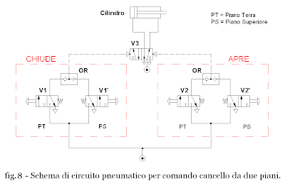
This problem can be solved in different ways and each solution requires the study to be analyzed before the elements necessary to achieve the required functions. For the movement of the gate is necessary that:
  • you use an actuator, in this case a cylinder, able to open and close;
  • that the cylinder can work in both directions.

The above conditions can be met by a double acting cylinder is positioned as shown in Figure 3.
The gate opens when the cylinder rod falls and closes when the cylinder rod is forced to leave. In other words, it is necessary that the flow of air under pressure alternately put the two chambers of the cylinder, also when a cylinder chamber is pressurized and the other must be discharging and vice versa. To reverse the flow using two selector valves that will be chosen to satisfy the above conditions.

In the first instance we can use two valves 3 / 2 NC monostable connected to the two cylinder chambers. Is obtained in this way the circuit diagram shown in Figure 4.

The V2 valve manually operated push button directs the flow of compressed air in the room right of the cylinder with consequent return of the stem moves the gate opening. On the contrary, the valve V1, which is also controlled manually, directs the flow of compressed air in the left chamber of the cylinder resulting in leakage of the rod that pushes the gate closes.
is easy to see that in both cases, when you release the button the cylinder chamber is not pressurized and the piston is not locked, that is pushing it moves. This is due to the fact that in the rest, the two valves connecting the chambers of the cylinder to exhaust. This situation makes us understand that we have found a solution to the problem proposed but we have not found the best solution.

<-- Previous Post Next Post ->

Sunday, October 28, 2007

How To Use Breville Compact Breadmaker

signals generated by the valves.

known as the selector valves are designed to guide the flow of compressed air cha get an attack. This flow of air directed by valve is said pneumatic signal.
If this pressure signal is used to control the switching another said valve control signal (Fig. 1).
If the signal feeds the chamber of an actuator, f acendo move such as the stem of a cylinder, then it is said power signal (Fig. 2).
A circuit of pneumatic automation to perform fully its role must and use both control signals and power signals, then it must contain both control circuits and power circuits which, in the diagrams , respectively, are indicated with dotted line and solid line. Given the different function, the control signals are usually low-pressure (p c Bar = 2 approximately) while the power at high pressure (p p = 6-8 bar approximately). In both cases, however, pressure is always determined by information on the operating characteristics of valves and actuators.


<-- Previous Post Next Post ->

Saturday, October 20, 2007

Powerpoint Poster Template A3

Introduction.

This blog is dedicated to the development of content concerning the unity of the F4 educational programming that is the technique of pneumatic circuits applied to simple handling problems. The cut chosen for the arguments is a very practical in order to help you better understand the use of basic pneumatic circuits. Last year, my students were very fond of the second subject treated in this way and I hope that somehow can serve you.

leave from real cases that become progressively more complex and I will describe some possible solutions for the handling by simple pneumatic circuits.


seems important to me, and not superfluous to specify that the topics covered in this blog are a simple introduction to industrial automation with pneumatic circuits (as clearly indicated by the module name F) as the treatment is aimed at students of the first two years of professional mechanic.

For further information please refer to the literature.

View the location of Unit F4 in Form F in order to address this unit you must meet the following prerequisites:


  • knowledge of the concept of gas pressure ;
  • Knowledge of circuit components for the generation, packaging and distribution of compressed air and their function;
  • knowledge and ability to distinguish the different distributors and valves their symbolism;
  • Knowledge of the function of flow regulators;
  • Knowledge and ability to distinguish the functions of the linear actuators and related symbols.

dudattica The content of this unit are:

or signals generated by the valves : control signals and power signals.
diagrams or simple tires. Main
or logic functions: OR , AND, NOT and YES , truth tables and the corresponding circuit elements.
or Automatic cycles: phase diagram, circuit diagram and realization of an automatic cycle.

<-- Previous Post Next Post ->

Monday, October 15, 2007

How Can Kasino Card Reader Write Protection

educational programming.

usually introduce the form of pneumatic in educational planning for the second year in mechanical operations. I will briefly below a record of annual programming.

educational programming for IPIA II
to address mechanical operation

Module A: Health and safety regulations.
- UD A1: Prevention and accidents in the workshop.
- UD A2: Work on the Machinery Directive.

Module B: State of the surfaces, tolerances and testing.
- UD B1: roughness and ridges.
- UD B2: Dimensional tolerances.
- UD B3: Geometric tolerances (Work).
- UD B4: tolerance system for threads (Work).
- UD B5: Measurements and testing.

module C: Manufacturing chip removal.
- UD C1: Characteristics of cutting tools.
- UD C2: fastening technology.
- UD C3: duty cycle.

Module D: Working for plastic deformation.
- UD D1: Production processes.
- UD D2: sheet metal working processes.

Form E: Introduction to CNC machines.
- UD E1: Anatomy of a CNC machine.
- UD E2: Mathematics of Numerical Control.
- UD E3: Functions and ISO programming.

Form F: Introduction to Automation - Principles of pneumatics.
- UD F1: Physical principles of gas and air.
- UD F2 generation and distribution of compressed air.
- UD F3: Use of compressed air.
- UD F4: Technique of pneumatic circuits.

Tuesday, October 9, 2007

Custom Enclosed Patio

Welcome!

Welcome to my Blog!
Just two words to clarify the choice of the title.
The main reason lies in the very theme of the blog and that is the 'Using multimedialit à in teaching. " The other in the desire to give a touch of originality to my work. I thought that would be perfect wrap up in one word the two terms MULTIMEDIA ' TEACHING and trying to find a word that transmit with a little' fantasy, both meanings. MULTIMEDIATTICA could be good. A salad! A term which, in my opinion, satisfy both objectives.
But this term does not exist - I thought. Why not use it then? More original than that!

After this brief introduction I present myself.

My name is Gianluca Ferraro and I am a mechanical engineer. Currently I teach in high school and attend the two-year specialization SILSIS at the University of Bergamo.

to be a teacher today.

My first day at school (teacher's mean) was traumatic. I thought of having to act like my teachers at the high school and my students would behave as I behaved myself with my professors.
We were wrong!

Multimedia teaching.

I realized over time that when the port in my notebook classroom attention of my students reach unimaginable levels in "normal" conditions. A Power Point presentation allows me an hour to more than ten hours of lecture. Multimedia represents a powerful tool available to teachers, but without the latter prevail over the traditional blackboard as, unfortunately, is increasingly the case in academia. Welcome
multimedia and goodbye chalk and slate? Absolutely not! I am convinced that the two schools of thought can coexist peacefully complement one another.

What I intend to do with my blog?

I will try to propose a series of lectures on the technical circuit peumatici contextualizing all in a second class to address IPIA mechanic.
Next Post ->